In Part three I will discuss and illustrate my installation.
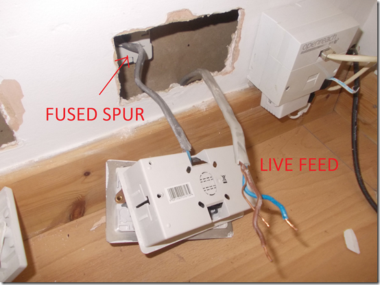
This is the corner of the living room near to the curtains. There are existing electrics in this area, in the form of a double wall plug socket which also connected to a fused spur on the other side of the stud wall in the porch area, which then connects to an outside porch light via another Z-wave switch. The Live Feed cable comes up from underneath the floor in the wall.
In this picture you can see I have already disconnected the Live feed cable from the back of the plug socket.
The first step was to connect the new Junction Box to the Live Feed, first turning off all the electric in the house at the consumer unit obviously.
Next I re-connected the double wall plug socket to the mains / junction box. Again this is not part of the curtain installation so that cable also has a red X on it.
Connecting the Fibaro Blind Control module to the mains
OK so now at this point I could start adding cabling for the actual curtain installation. Next to the double plug wall socket, I had an existing cut out in the wall for an AV cable (Sub woofer) which I don’t actually use. So I am going to utilise the space behind here to put in the Fibaro module. (Or I could have put the Fibaro module behind the new wall switch for the curtains higher up the wall, but that would have meant feeding more cables up inside the wall than I need too).
I looped around a short piece of socket twin and earth cable as you can see in the photo below, connected the brown wire to the Live connection on the Fibaro module and the blue wire to the Neutral connection on the Fibaro module. The earth cable(s) you can see are not required and were cut off.
Next step was to connect the other end of the short loop cable from the Fibaro module into the mains / junction box (Live and Neutral).
Connecting the Wall Switch to the Fibaro module
Next step was to add some cable from the Fibaro module to the wall switch, using the S1 and S2 connections on the module.
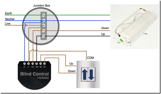
The wiring diagram below shows the Live mains cable going from the junction box in to the Fibaro module (as in the picture above) but then also a second live cable coming from the module and going to the COM connection on the wall switch.
Due to the thickness of this socket wire I was unable to physically fit two live cables in to the one live connection hole on the module.
So in the picture below I had to use a little connection block. You can see two Live cables going in to the small connection block and then one little cable connecting to the Live (L) connection on the module.
You can also see as well the Neutral from the mains connecting to the Neutral (N) connection on the module.
Also we have two cables S1 and S2 which will connect to the wall switch.
Here is the back of the wall switch.
The brown Live cable is coming from the Fibaro module. As are the other two cables coming from the S1 and S2 connections on the module.
Note:- I used a triple+earth cable for the connection from the module up to the wall switch, which has a brown, black, grey and earth cable.
From the user manual:
Using momentary switches:
“Clicking UP button connected to S1 terminal, initiates up movement. Clicking button connected to S2 terminal, initiates down movement.
If the blind is moving, each click, of any button, will stop the movement. In addition a button click sends a command frame to I-st association group devices. In case of venetian blinds, it’s possible to manage the lamellas angle. Operating Mode - Venetian Blind, or Parameter 10 value set to 2.
Holding connected to S1 terminal initiates lamellas rotation up. Holding connected to S2 terminal initiates lamellas rotation down. In addition a button hold sends a Fibar Command Class control frame to II-nd association group devices.”
Connecting the Fibaro module to the curtain motor via the Junction box
In this picture you can see I’ve added another cable to the O1 and O2 connections on the Fibaro module. The O1 and O2 connections are the switched live to open or close the motor / curtains.
This cable then loops round in the wall and connects to two empty connections in the junction box, the curtain motor will then connect to these wires to open and close the curtains.
Connecting the curtain motor
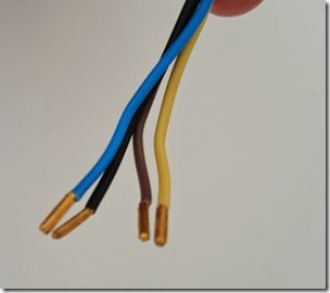
The curtain motor has four cables coming from it, the blue Neutral and the yellow Earth will connect to the Neutral and Earth connections in the junction box.
The other two cables (brown and black) are for switched live for opening and closing the curtains. These will connect to the O1 and O2 connections on the Fibaro module via the junction box.
In this picture you can see how the curtain motors four cables would connect to the junction box.
In this picture you can see the white curtain motor cable. These are the four cables from the curtain motor now connected in the junction box.
In this configuration when I press up on the wall switch (L1) the curtains open, when I press down on the wall switch (L2) the curtains close.
Lid back on the junction box ready to be put in the wall.
Mounting the curtain rail
This is the regular curtain pole that I had to take down.
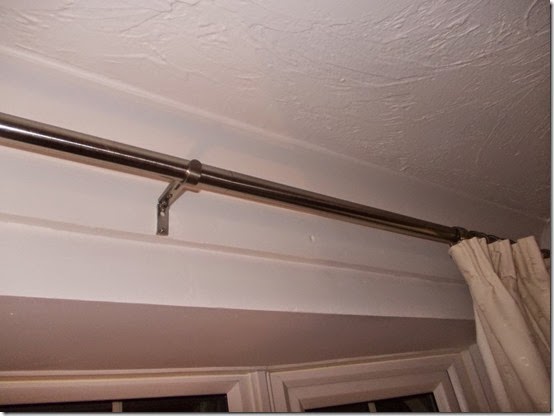
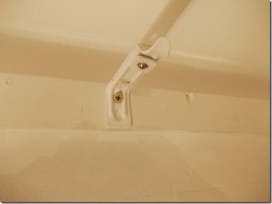
I marked out where I wanted the new wall mount brackets to go and screwed them in to the existing wooden batten on the wall.
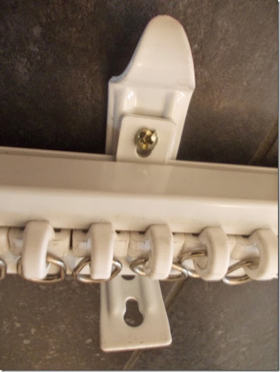
You then have to clip the rail in place in to the brackets and position and tighten up the square metal washers that hold the rail up. A little tricky!
In this photo its not attached to the wall but you get the idea!
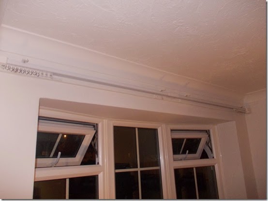
New curtain rail now mounted on the wall
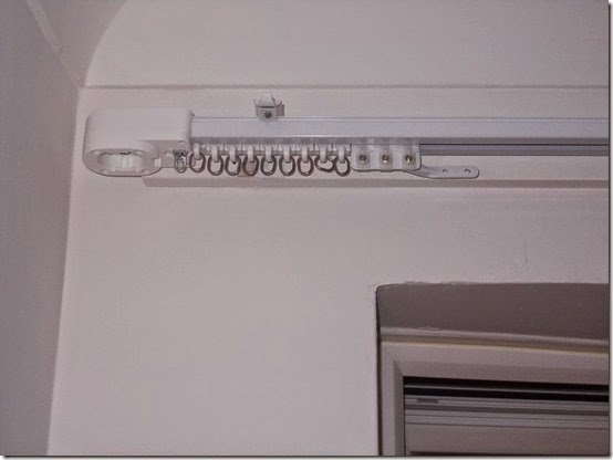
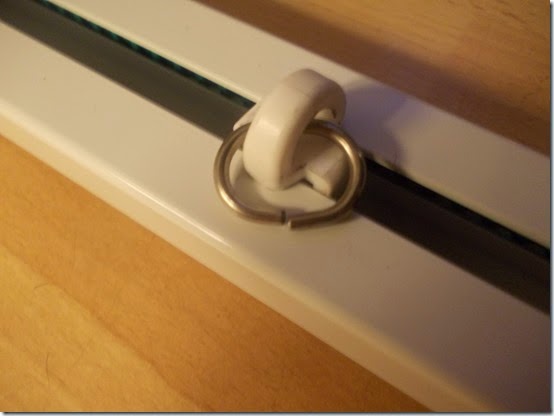
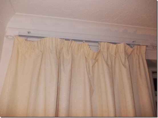
I only got nine of these sliding hoops on each side. Which isn’t enough, I need at least 12 on each side for the curtains to gather properly at the top and look OK. I’ve had to contact the seller to see if I can get some more? Which is a pain, so double check when you purchase how many hoops your getting and if its enough?
As you can see I need more hoops, the wife wasn’t impressed with this LOL. I don’t know if these can be bought from any regular curtain store or if I’ll have to wait for some more to come from China? I will take one of the hoops out of the rail if possible and take it round the local stores I may get lucky.
You can also see on the far left hand side that the motor isn’t attached yet.
Update from Seller: "We normally arrange 6 runners per metre and for buyers from the EU, we always arrange 8 runners per metre."
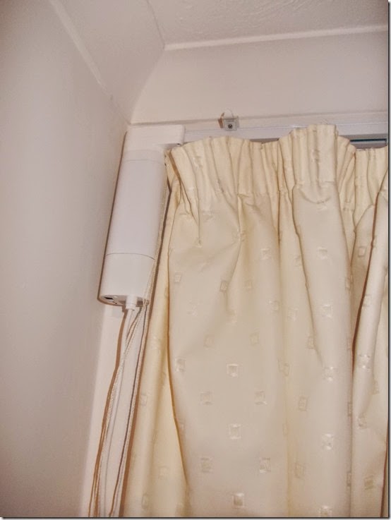
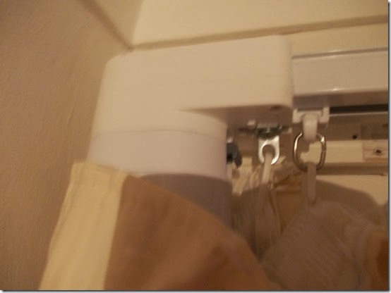
Motor now attached - Initially I had it looking like this and the motor was showing.
I quickly realised I had to wrap the curtain right around the motor and hook it on from the back instead.
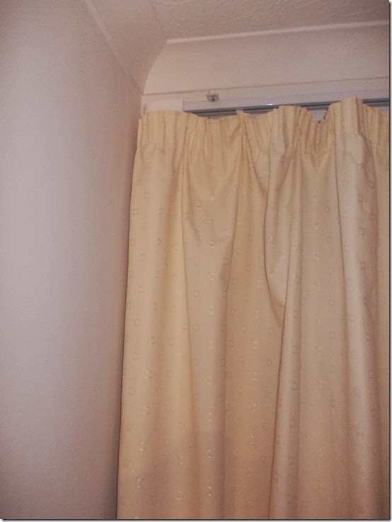
So now it looks like this which is better as the motor is concealed.
That’s it for part three. In part four I’ll probably show the wall switch installation and how I’m planning on hiding the cable from the motor inside the adjacent stud wall. I haven’t actually done this yet, I may start that work tomorrow.
Part five will be the Vera Z-wave setup and some other cool stuff!
Part four here.








No comments:
Post a Comment